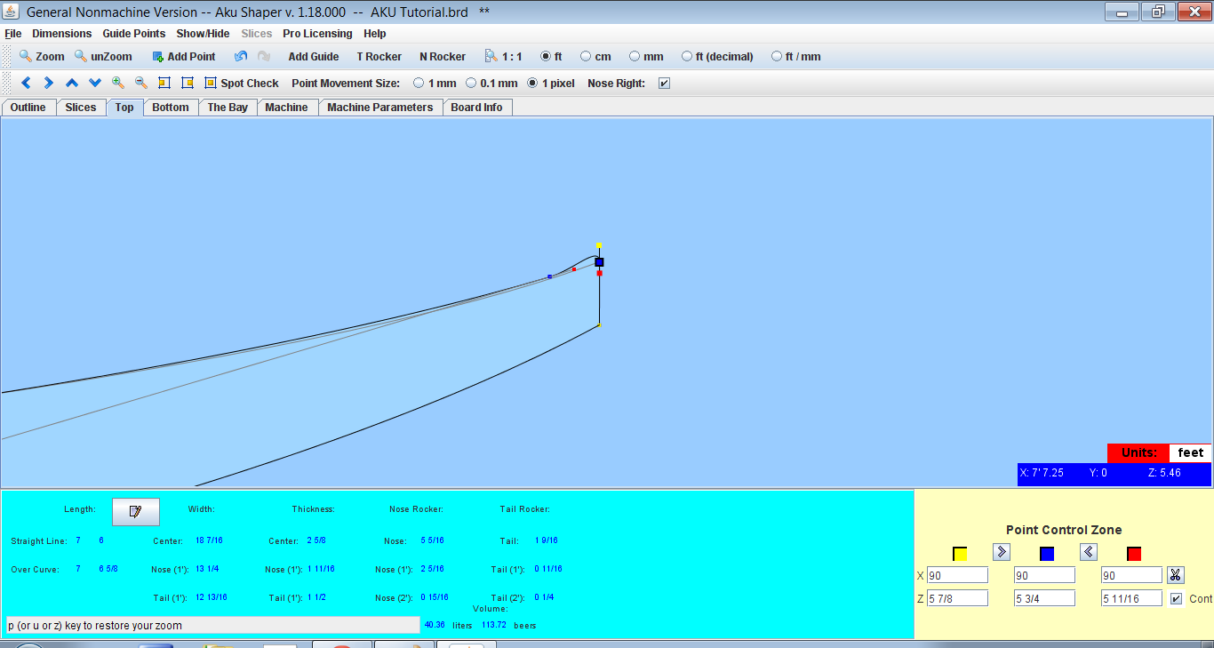
We can also click on the bezier point and use our arrow keys to move it around. We release the mouse button to release the point when we’re happy with its position. To move an existing point, we hover the mouse pointer over it, hold down the left mouse button, and move the point to where we want it. Existing bezier points can also be moved.

Bezier points can be added to the bottom curve of the plan shape to get it match the shape of the image board. We'll do this by moving the bezier points (blue dots) which are located on the board outline. The next step of the process is to adjust the board outline. The image is hiding behind the board outline. For the tail, we hold down the “t” key of our keyboard, hold our mouse pointer over the tail of the board on the image and left click our mouse. To line up the image board, we hold down the “n” key on our keyboard, hold our mouse pointer over the tip of the board nose on the image and left click our mouse. The dialogue box for aligning the image board. Remember we can always change the board size at any time while we are designing in AKU.Ĭlick, we choose the directory where we saved our board plan and profile image.

We'll select the size that is closest to the final size of board, about 8'.

The board size template that is chosen will depend on what size board is required. There is also a reference card in the categories.Ĭlick in the drop down box and click OK. Click on the "Help" menu option and then "Help" again. There are also some tutorials to get you started as well. You should end up with a screen like this.īefore we get back into the tutorial, I wanted to mention that AKU does have a help option that has some good reference information. This may take a few minutes so please be patient. I had to flip the board 90 degrees to line up the nose and tail with the board direction in AKU. This will be the board image which we will base our design on. I've saved the board image to my laptop and then edited it in Microsoft Paint to make sure that the nose of the board is pointing to the right hand side of the computer screen. For the purposes of this tutorial I've used Google images and found an image of a rounded pin tail that I like. We could photograph a board or find a picture on the Web. I had bought templates for 5 m wood boat.that took 500 hrs to build.Designing Hollow Wooden Surfboard Templatesįirstly, we need to find a picture of a board plan shape and profile (rocker) that we like. Totally do- able.I've done it back in pre CnC days, actually pre computer days. Other way is to print out on many peices of paper, tape together, glue them to masonite and cut with jigsaw and then file or sand them down to line. I am arranging parts on the 4x8 masonite for the CnC machine. The templates are too long, so the outline and profile curves have to be split in half lengthways to fit. so I create an artboard ( page size) that is 4x8 and place the template outlines on the artboard. This cannot be cut out of a 4x8 ft sheet of masonite. Then I know they are clean.Īt this point I have profile ( side view of rocker and deck) and outline ( top view) of entire board. So I just use the imported dxf curves as guides and redraw them in illustrator. You can tell the math is getting corrupted.

I have found that curves can be converted to line segments, which are not accurate.Īlso, the curves are really messy, segmented and lots of control points. When I export the 3d files from solid works or Shape 3d, I then open those files in Illustrator.


 0 kommentar(er)
